


TL;DR — Quick Summary
Video Lessons
Current
The rate of flow of electrons or charges through an electric circuit per unit time is called Current. Its SI unit is Ampere (A).
Types of Current
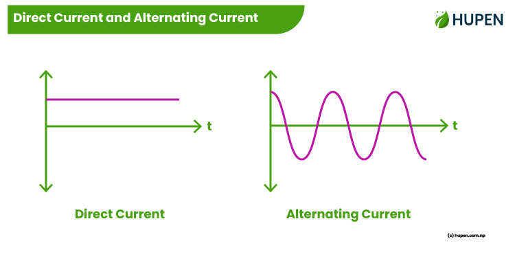
There are two types of current viz. Direct Current (DC) and Alternating Current (AC).
1. Direct Current (DC)
If the magnitude and direction of the current do not change with time, then it is called direct current. In DC current always flows in same direction. Dry cell, Battery etc. are the sources of DC.
2. Alternating Current (AC)
If the magnitude and direction of the current do change with time, then it is called alternating current. In AC current always flows in same direction. Generator, Dynamo etc. are the sources of AC.
Magnetic Effect of Electric Current
When an electric current is passed through a conductor, the magnetic field is produced around the conductor. This is called Magnetic Effect of Electric Current.
Magnetic Field Around a Current Carrying Straight Wire
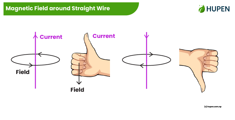
When an electric current is passed through a straight wire, the magnetic field is produced around the wire. The direction of the produced magnetic field depends on the direction of the current in the wire. The direction of the produced magnetic field can be easily determined with Maxwell’s right-hand thumb rule. According to this rule, point your right thumb in the direction of the current and your curled fingers will show the direction of the magnetic field lines around the current-carrying wire.
Magnetic Field Around a Current Solenoid
When an electric current is passed through a solenoid, the magnetic field is produced around the wire. The North Pole (N) is produced at one end of the solenoid and the South Pole (S) on another. The direction of the produced magnetic field depends on the direction of the current in the wire. The direction of the produced magnetic field can be easily determined with Maxwell’s right-hand grip rule. According to this rule, point your curled fingers in the direction of the current and your thumb will show the direction of the magnetic field lines around the current-carrying wire.
Magnetic Flux
The number of magnetic field lines through the given closed surface is called Magnetic Flux. It is denoted by Greek letter Phi. Its SI unit is Weber (Wb).
Motor Effect
When a current carrying wire is placed in the magnetic field, a movement is developed in the wire, which is called Motor Effect.
Electromagnetic Induction
The production of electric current through a wire, when changing magnetic field is applied is called Electromagnetic Induction.
Faradays’ Law of Electromagnetic Induction
The law states that “the magnitude of the electric current is proportional to the rate of change of the magnetic flux that cuts across the circuit”.
Transformer
The device which is used to increase or decrease the magnitude of emf, or voltage is called transformers. The transformer converts low AC voltage to high AC voltage and vice-versa.
Types of Transformers
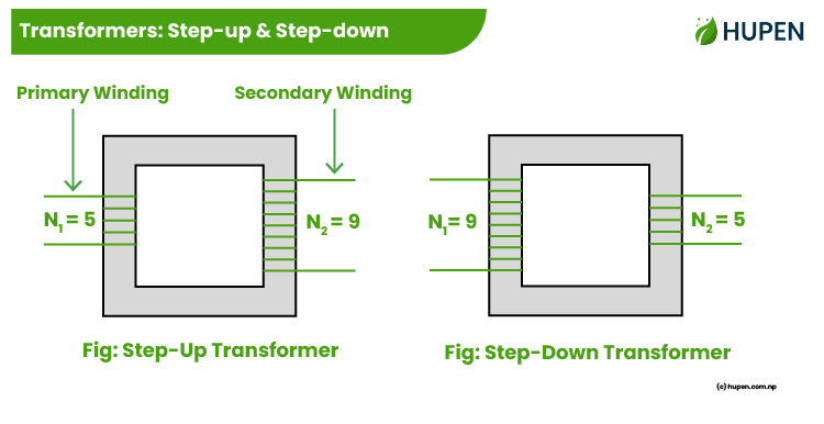
There are two types of transformers viz. Step-Up and Step-Down
1. Step-up Transformer
The transformer which converts low AC voltage to high AC voltage is called a step-up transformer. It increases the magnitude of alternating emf. In step-up transformer, N2>N1 and V2>V1. It is used in power houses.
2. Step-down Transformer
The transformer which converts high AC voltage to low AC voltage is called a step-down transformer. It decreases the magnitude of alternating emf. In step-down transformer, N1>N2 and V1>V21. It is used in electric circuits.
Working of Principle of Transformer
The transformer is based on the principle of mutual induction or electromagnetic induction. It is based on following two principles
- Input energy is equal to output energy i.e I1V1 = I2V2
- Voltage is directly proportional to the number of turns of wire
In a transformer, the ratio of number of turns of wire in primary to secondary coil is always equal to the ratio of the voltage in primary to secondary coil. Let us consider Np and Vp be the number of turns of wire and voltage in primary coil respectively. Also let us consider Ns and Vs be the number of turns of wire and voltage in secondary coil respectively. Then
Important Formula in This Chapter
Np/Ns = Vp/Vs
Where,
Np = Number of turns in primary coil
Ns = Number of turns in secondary coil
Vp = Primary Voltage
Vs = Secondary Voltage